Article content
The formwork for a concrete arch has an awkward assignment: it must hold the shape of a structure that is not yet strong enough to hold itself.
At a small bridge, the solution might begin beneath the arch. Build a temporary support from the ground, place the forms on it, pour the concrete and remove the support once the permanent structure can carry its load. Change the setting to a deep reservoir between steep mountains, then stretch the arch across 600 metres, and that seemingly straightforward idea becomes a very different proposition.
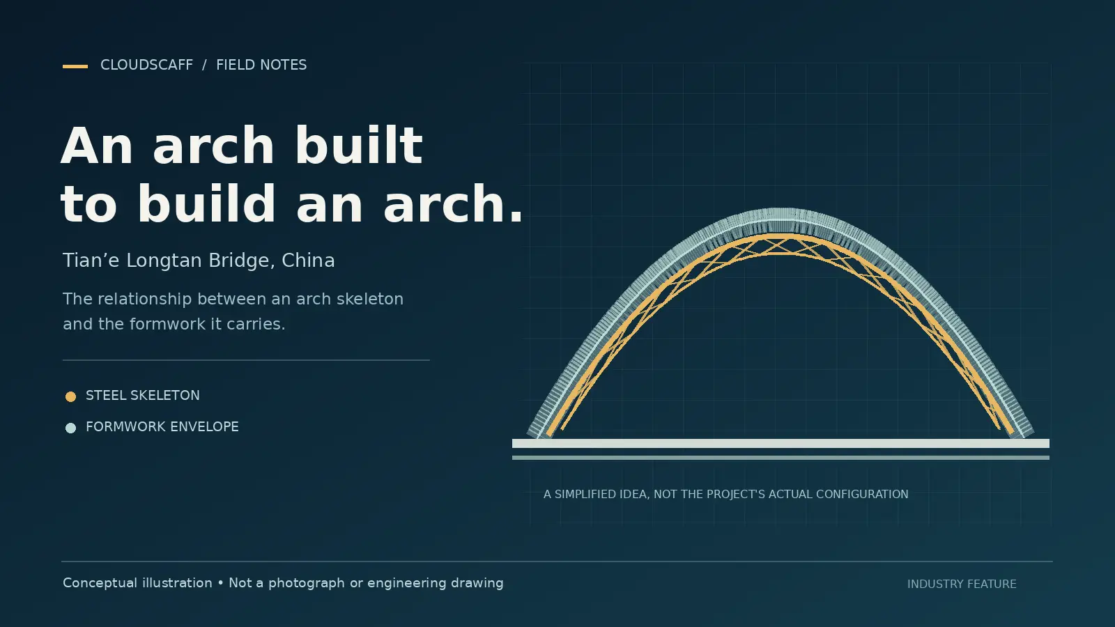
The Tian’e Longtan Bridge in Guangxi, China, offers one answer. Before the massive outer concrete arch was complete, a steel-tube skeleton was assembled across the gap. It helped carry the formwork and construction loads; ultimately, it remained embedded within the finished arch.
That description compresses years of engineering into a single sentence. The interesting part is not simply that a skeleton existed. It is that its job changed as construction progressed. It had to be built, supported, loaded, surrounded by concrete and eventually integrated into the permanent structure. Each stage changed what the next stage could safely depend on.
The bridge opened to traffic on 1 February 2024. The Chinese government's report describes a four-lane crossing over the Hongshui River, with a total length of approximately 2,489 metres. Its length and its 600-metre main arch span are different measurements, a distinction that matters whenever record claims are discussed. Chinese government/Xinhua opening report
This is a historical project feature, not an erection manual. Every temporary structure must be designed for its own site, loads, sequence, equipment and applicable local requirements.
The finished view hides the temporary problem
Pictures of the completed crossing show a clean arch below a long road deck. The result looks resolved: stone-coloured concrete, a continuous profile and traffic moving across the top. Construction photographs tell a more complicated story. Before a deck could use the arch, the arch itself had to come into existence above the reservoir.
The setting made the question of support particularly significant. In a 2026 engineering account, Jielian Zheng and Chun Zheng describe a reservoir channel bordered by steep ground. Their paper identifies Tian’e Longtan as a steel-reinforced concrete arch and describes the principal challenge as building the arch rib itself. Advances in Bridge Engineering, 2026
For anyone who supplies or installs falsework, the distinction between a finished load and a construction load is familiar. A completed member may be able to perform its permanent role, yet the material placed to form it must be supported before it develops that capacity. At this scale, those intermediate conditions become the project rather than a minor detail of it.
The question is not merely where the concrete goes. It is where the working platforms go, what holds the forms, how a changing load reaches the foundations and what happens while the two sides of an incomplete arch are still advancing. The final silhouette answers none of those questions by itself.
A steel arch before the concrete arch
Zheng's 2024 paper describes the general stiff-skeleton approach: erect an arch skeleton first, suspend formwork from it and place the enclosing concrete in stages. At Tian’e Longtan, the skeleton incorporated concrete-filled steel tubes. Once the surrounding concrete was complete, the skeleton remained inside the arch instead of being recovered as conventional temporary falsework. Engineering, 2024
The word “temporary” needs care here. The formwork and working platforms were temporary construction equipment. The skeleton was a construction-stage support with a continuing structural role. Calling the entire assembly disposable temporary works would miss an important part of the design.
Imagine, as a simplified analogy, a shaped frame that first provides a working surface for building a heavier shell. As the shell gains strength, the two can act together. The analogy helps explain the sequence, but it is not a description of the bridge's engineering details or an instruction for another job.
This is one reason the project is interesting to the formwork sector even though few contractors will ever work on a 600-metre arch. It makes an everyday dependency unusually visible: formwork is never just a surface that touches wet concrete. Its design depends on what supports it, when loads arrive and where those loads go next.
Getting the first structure across the gap
The 2026 account describes the skeleton as fabricated in segments and transported to the site by water. The segments were erected using a cable-supported cantilever assembly arrangement. That sequence matters because a support system does not appear fully formed on the first day. It, too, needs a construction method. Zheng and Zheng, project overview
This creates a layered logistics problem. A segment must arrive with the right geometry and connections, but it also needs a lifting route, a temporary position and a sequence that makes the next segment possible. The project team is managing a series of incomplete structures, each with its own condition, before it can manage the completed arch.
For a reader accustomed to conventional building slabs, the contrast is striking. On a repetitive floor, a formwork set may travel upward through similar bays. On this crossing, the support geometry follows a long curve over open space. Location and sequence are inseparable: the same type of component may play a different role depending on where and when it is installed.
It would be tempting to describe the cable system as a simple substitute for ground-supported falsework. That would flatten the engineering. The decision involved a coordinated permanent structure, temporary supports, lifting and construction sequence. None of those elements can be assessed responsibly in isolation from the rest.
Why not pour the entire arch at once?
Concrete is heavy before it has become the finished structural member. Placing a very large amount on a partially completed support changes the forces in that support while the project is still underway.
The engineering account reports that the encasing concrete was arranged in layers and working areas rather than placed as one continuous operation. It describes eight working platforms, with four used for placement while others could be prepared for reinforcement and formwork work. These are project-specific decisions, not a recipe for other bridges. 2026 technical note
To see why the sequence matters, consider a hypothetical pair of work areas on opposite sides of an arch. If one advances ahead of the other, the temporary support may experience a different condition from the one expected when both progress together. The correct response on any real project depends on the engineer's design and monitoring plan; the point here is that the order of work changes the structure being worked on.
For formwork suppliers, this shifts attention away from a single impressive quantity and towards repeatable movements between states. A platform must be ready when required, but preparing it must fit the reinforcement, concrete supply, access and inspection sequence. A delay at one location is not merely a local inconvenience if the overall plan depends on coordinated work elsewhere.
The published account is written by engineers associated with the project. Its conclusions about the chosen arrangement should be read as their project analysis, not as an independent comparison proving that one sequence is universally best.
A platform is more than a place to stand
The phrase “working platform” can sound interchangeable with “walkway”. On a major concrete placement, the platform is part of a wider working environment. It needs to accommodate the people and operations assigned to it, connect safely to access routes and remain compatible with the formwork and reinforcement around it.
The exact configuration at Tian’e Longtan belongs to the project's approved documents. The published papers provide a useful overview but do not give an outside reader permission to reconstruct an installation. This article therefore does not prescribe platform capacities, tying arrangements or erection details.
What the case does show is the value of considering a platform as part of a sequence. A platform prepared for reinforcement is not necessarily in the same state as one ready for concrete. A form face that can be installed at one stage may obstruct another activity later. Access needed for inspection may differ from access needed for removal.
Those distinctions matter on much smaller projects too. A contractor planning a retaining wall, a tank or an elevated transfer slab might never face the geometry of this bridge, but still has to coordinate the changing roles of forms, supports and work areas. The lesson is conceptual, not a claim that the same engineering solution should be transferred.
When the model is not the bridge
The team's research extended beyond the full-size site. A 2024 study reports a large-scale physical model test designed around the bridge's construction process. The researchers simulated progressive placement of the outer concrete and monitored changes in stress and movement. Case Studies in Construction Materials, 2024
That detail is easy to misread. A model test is an experiment under specified conditions. It is not itself a field measurement of every component on the real bridge, and a result obtained at model scale is not a universal allowable value.
Its value lies in the questions it can help researchers investigate. What changes as material is added? Where does the structure move? How do the model's observations compare with the assumptions used to plan the work? On an unusually ambitious project, those questions deserve attention before the site team relies solely on a drawing of the final structure.
For industry readers, the practical distinction is between evidence and reassurance. Saying a concept was tested does not eliminate the need to understand what the test represented and what it did not. It also does not establish that a different contractor's system will behave the same way.
Concrete placed at different times has different histories
The formwork operation does more than create a geometry. It also determines when adjacent portions of concrete are placed and when the forms can move. Different placement dates mean different ages and different stages of material development across the work.
The 2024 Engineering paper identifies cracking control as a significant issue in staged encasing concrete. A separate research paper examines stresses at concrete interfaces during construction using the Tian’e bridge as its case study. Construction research
The connection to formwork is direct, even if the underlying material science belongs to specialists. Formwork drawings, reinforcement details, concrete supply and the planned sequence cannot be treated as unrelated packages that happen to meet on site. The position of a joint or the time at which a form can move can affect what the next team is able to do.
That does not mean a formwork contractor alone is responsible for the concrete design. It means that useful coordination happens before installation: the designer, contractor, concrete team and access specialists need a common understanding of the stages they have actually been asked to deliver.
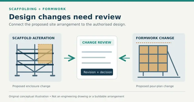
For a hypothetical smaller project, if a contractor proposes changing the order of two pours because one formwork set arrives late, the first question is not whether the equipment can physically be moved. It is whether the revised sequence has been assessed and accepted by the responsible designer. This is an example of a decision point, not a claim about an incident at Tian’e.
The history behind a seemingly new idea
Using a structural skeleton to assist construction is not unique to a single bridge. What changes is the geometry, materials, scale and sequence, along with the analysis needed to understand the construction stages.
The American Society of Civil Engineers describes an earlier example at the White River Concrete Arch Bridge in Arkansas. Its historical account says prefabricated steel ribs helped form and reinforce the concrete arches, while a cable system moved materials over a difficult river crossing. ASCE historical landmark
The two bridges should not be presented as the same design. They were built in different places and eras, with different spans, structures and methods. The useful connection is narrower: both show engineers responding to the difficulty of placing and supporting concrete above water by thinking carefully about what could be assembled and supported before the concrete was complete.
Another comparison comes from Spain's Contreras Reservoir railway bridge. An engineering abstract describes its arch being built by free cantilever with temporary support, while separate scaffolding trusses helped construct the deck. American Concrete Institute abstract
These examples are not a league table. They demonstrate that “bridge formwork” covers many different problems. An access scaffold for repairs, a movable support for a deck and a form suspended from an arch skeleton may all sit under the broad temporary-works conversation, but their purposes and design obligations are not interchangeable.
The record is a point in time
The bridge's 600-metre arch was reported as a record for its category at opening, and the 2026 engineering note describes it as the longest-span arch bridge. Records depend on definitions, verification and the date of comparison. A steel-reinforced concrete arch, a steel arch and a high-speed railway arch are not necessarily competing for the same title.
The distinction between total bridge length and main span is equally important. A long crossing may include approaches and many spans; the main arch span measures the distance associated with that particular principal opening. Mixing the figures can create a more dramatic sentence while making the engineering harder to understand.
The bridge's real story is strong without stretching the record claim. A team assembled a structural system over a difficult reservoir and then used a planned sequence to surround it with concrete. The public can see the result in one glance. Understanding how it was built requires following stages that are no longer visible.
The hidden business of sequence
There is a commercial lesson here, but it does not require an inventory checklist or a software pitch. Large, complex construction depends on specialist knowledge that is often invisible in photographs of finished buildings and bridges.
For a formwork company, the question behind a headline project is not only “What system was used?” It is also “What did the system have to enable at each stage?” A tender drawing, a transport plan, an installation method and a removal plan all describe different parts of the same temporary existence.
On a major arch, formwork can be surrounded by a permanent structure. On an ordinary building, it may be stripped and moved to the next floor. In both cases, its value lies in enabling work to proceed in a controlled way. The finished concrete surface may be what the public remembers, but the ability to create that surface depends on decisions made long before the pour.
It is also worth resisting the assumption that the biggest project automatically provides the best answer for a smaller one. An engineered permanent skeleton may make sense in a deep reservoir crossing while being entirely inappropriate for a short wall. The transferable skill is the discipline of understanding support and sequence, not copying a distinctive piece of equipment.
From construction support to permanent structure
The striking feature of Tian’e Longtan is the relationship between what was needed during construction and what remained afterwards. The skeleton was not a simple temporary prop waiting to be removed. Nor was it merely a hidden finished component with no earlier role. It participated in the bridge's development.
That dual role changes how one reads the project. A project photograph showing exposed steel is not simply an unfinished version of a concrete arch. At that point, the visible frame was doing work that allowed the next material to be placed. Later photographs show a different stage, with the skeleton enclosed and the external form transformed.
For the scaffolding and formwork industry, this is an invitation to look beyond the final image. The most consequential structure on a site is sometimes the one whose job changes several times before completion. Understanding those changes is what turns a dramatic span into a construction story.
Frequently asked questions
Where is Tian’e Longtan Bridge?
It is in Guangxi, southern China, crossing the Hongshui River reservoir area. It opened to traffic in February 2024.
Is the 600-metre figure the length of the entire bridge?
No. It refers to the main arch span. The complete bridge, including its approaches, is approximately 2,489 metres long.
Did the steel skeleton remain in the bridge?
The published engineering account says the concrete-filled steel-tube skeleton became embedded within the completed encasing concrete. Temporary forms and working platforms should not be confused with that permanent structural skeleton.
Was this ordinary ground-supported falsework?
The published description is of a staged arch-skeleton method with formwork carried from the skeleton. It is not evidence that an ordinary ground-supported falsework arrangement could simply be substituted.
Can contractors use the published sequence as a design?
No. These papers describe a specific engineered project. Any new bridge or temporary support needs project-specific analysis, competent design, approved methods and compliance with the rules applicable at its location.
Sources and further reading
- Chinese government/Xinhua: bridge opens to traffic, 2 February 2024.
- Zheng and Zheng: Key innovations in the construction of Tian’e Longtan Bridge, 2026.
- Zheng: Recent Construction Technology Innovations and Practices for Large-Span Arch Bridges in China, 2024.
- Large-scale model test on the construction process of a stiff skeleton arch bridge, 2024; TRID publication record and abstract.
- Evolution of concrete interface stress under construction, 2023.
- ASCE: White River Concrete Arch Bridge.
- ACI: Contreras Reservoir railway arch bridge.