Article content
In the Port of Las Palmas, crews are casting a concrete foundation for an offshore wind turbine on a worksite that already floats. The surprise for formwork teams is how much of the kit was designed to come back off the concrete and go round again.
The 6 MW prototype, called WHEEL, was still under construction at the León y Castillo Poniente quay when project lead Esteyco reported on it on 26 October. Ten days earlier, formwork supplier ULMA released details of the build. The two accounts put a useful part of the offshore wind story in view: before a turbine can be towed to sea, someone has to work out how to pour its foundation, how crews will reach it and where the forms go next.
A floating worksite for a floating foundation
There are two floating structures in this story. One is a modular construction barge, called AIRBARGE. The other is the turbine’s permanent floating foundation. Rover Maritime is building the concrete foundation on the barge in port. The finished prototype is planned to go offshore; the barge serves the build.
According to ULMA, the foundation has two concrete tanks connected by cables. The larger upper tank, 41 metres across, provides buoyancy. A narrower, 14-metre lower tank provides ballast to help stabilise the assembly. The idea of using concrete for a float sounds counterintuitive until you picture the hull of a ship. Weight matters, but so does the volume of water the structure displaces.
A concrete crew on a barge also has a constraint that most land sites don’t. The platform’s level and how deeply it sits in the water can change as work progresses. Esteyco’s construction update describes a barge built from modular units with separately controlled ballast groups. That gives the team a way to control how the work platform sits through successive stages, rather than treating it as an ordinary slab on land.
The same circle needed two different sets of forms
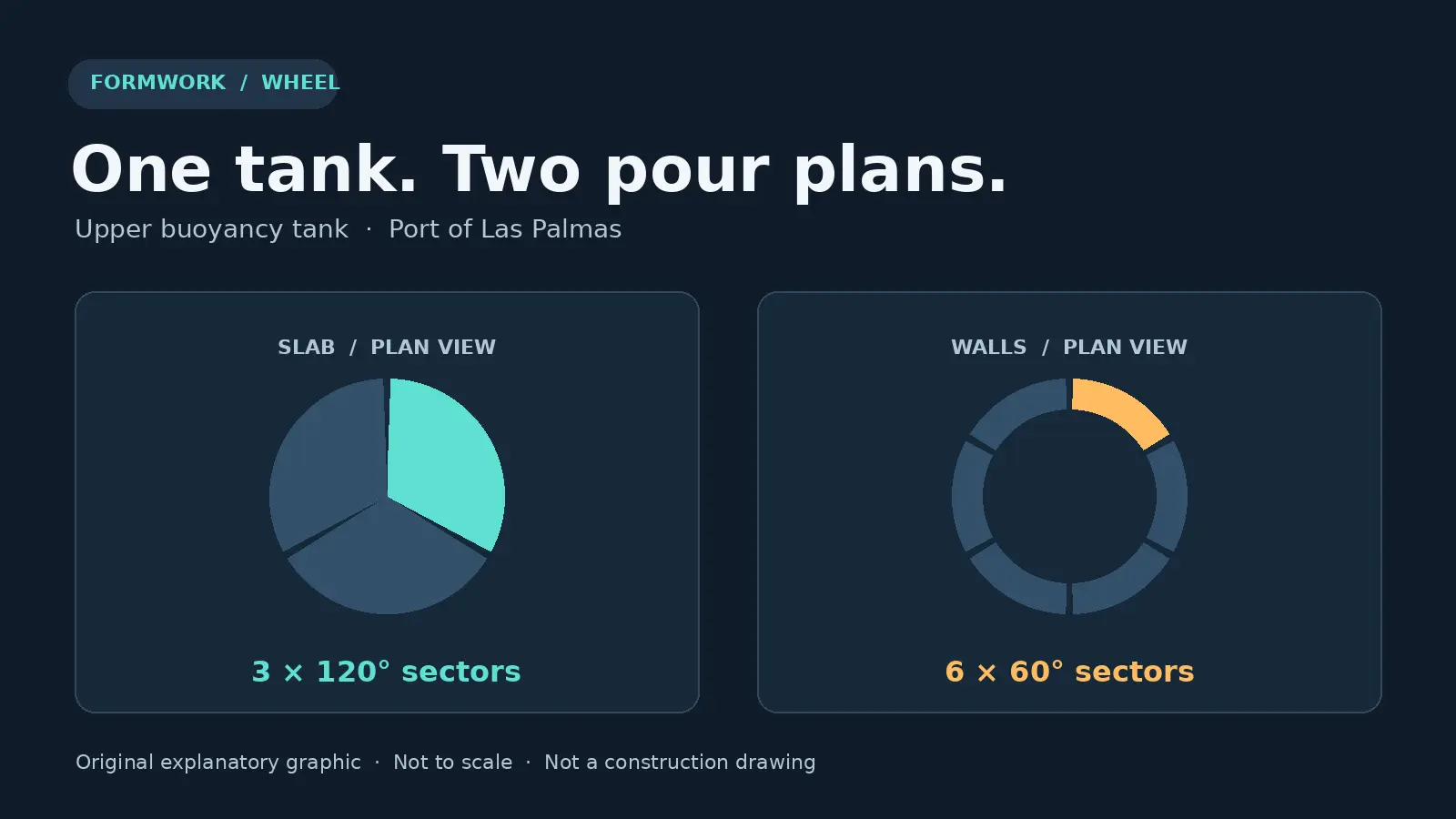
Look down at the upper tank in plan and the first surprise is how differently its base and walls were divided.
For the base, ULMA describes three 120-degree sectors. Its system used specially made curved walers, the backing members that support and align the forms, along with permanent polystyrene formwork in the centre. Rover Maritime reported in June that the base slab used 350 cubic metres of concrete in total. The contractor singled out the coordination between the batching plant and site crew: keeping the supply in step with placement was part of the job.
For the walls, the plan was six 60-degree sectors. The supplier combined adjustable circular forms with modular panels so it could move and reuse most panels across successive pours. A sector is part of the circle in plan, not a level of the wall. Those two divisions, three for the slab and six for the walls, tell you why the forms for one stage could not simply be carried forward unchanged.
The parts that stayed behind were just as deliberate. Custom steel moulds produced precast slabs for the upper tank roof. The steel moulds were tooling; the precast slabs became permanent formwork for the concrete topping. Multidirectional scaffold provided working platforms and access as the work moved around the tank. It served the build but was not part of the finished foundation.
What the prototype still has to prove
The project’s plan is to assemble the prototype in port, then tow it to the PLOCAN test site off Gran Canaria. Spain’s official gazette records a July prior administrative authorisation for the installation and power connection. That is a milestone, not evidence that the turbine has been installed or is generating electricity.
Nor does one prototype establish how cheaply a fleet could be built. The lesson already visible at Las Palmas is more specific: when a shape repeats, you can design around the next use of the form instead of building every mould from scratch. The real test is whether you can strip and move the kit when the next stage needs it. On a floating worksite, that question stops being an afterthought.
Lead illustration: original CloudScaff graphic, based on ULMA’s published sector counts. Not a construction drawing.
Frequently asked questions
Is the construction barge part of the finished turbine?
No. AIRBARGE is the platform for building the concrete foundation. WHEEL is the assembly intended for offshore testing.
Why were the slab and the walls split differently?
ULMA describes three sectors for shaping the curved slab and six wall sectors that allowed most panels to move between pours. The sectors represent a breakdown of the work, not six layers of concrete.
Is WHEEL already operating offshore?
The October project update described WHEEL as under construction in port. It identifies PLOCAN as the planned test site.